|
The IP Security Protocol (IPsec) and the Internet Key Exchange (IKE) protocol are designed to permit system and network administrators the capability to protect traffic between two systems. These systems can be network devices or individual hosts. With the release of Solaris 8, Sun added the ability to configure IPsec on Solaris hosts in order to construct a virtual private network (VPN) between the systems or to secure the traffic destined for a system. This article is the first of a three-part series that will examine IPsec and the key management protocol, IKE, and provide readers with an introduction on how to configure both protocols on a Solaris host.
IPsec and IKE
Before delving into how to configure IPsec and IKE on a Solaris host it is helpful to understand how IPsec and IKE came into being, as well as how the two systems work.
IPsec
In the mid-1980s network designers began to realize that the 32-bit address space provided by IPv4 was insufficient. As a result of this realization, the IETF, in the early 1990s, decided to design a new version of IP, IPv6, to replace IPv4. One of the key features of IPv6 was additional security at the network layer. The designers of IPv6 had the benefit of experience with IPv4, which was created with no security in mind. IPv6 would provide the capability to secure the communications between multiple hosts. This became known as IP Security or IPsec. Initially the IPv6 designers wanted to prohibit the back-porting of IPv6 features to IPv4 as a way of encouraging users to migrate to the new protocol. The designers of IPsec, however, did not care whether IPsec was deployed in an IPv4 or an IPv6 environment and therefore designed the security protocol to work in either.
Application-specific security has developed in many areas - e-mail (S/MIME, PEM, PGP), authentication (Secure Remote Password (SRP), Kerberos), Web applications (SSL), and remote access (SSH) to name a few. IPsec implements security at the network layer and provides for real-time communication security. By securing the communication at the network layer, IPsec provides security both for applications which already have security mechanisms as well as those which do not.
IPsec Framework
IPsec has many uses, from providing secure connectivity to a remote site across the Internet to securing remote access over the Internet to enhancing e-commerce security. IPsec consists of a framework of security protocols and information exchanges designed to facilitate secure communications. There are three IETF RFCs that form the basic foundation of IPsec:
RFC 1825 - Security Architecture for the Internet Protocol
RFC 1826 - IP Authentication Header
RFC 1827 - IP Encapsulating Security Payload
Note: These three RFCs have since been updated as RFCs 2401, 2402, and 2406 respectively.
The rest of this section will discuss the two protocols available in IPsec, the communication modes IPsec provides, and the concept of a security association and how it is used in IPsec. Critique of the complexity of IPsec or the redundancy and overlap of some of its features is beyond the scope of this article, instead the reader is refered to Network Security - Private Communication in a Public World (see [KPS02] in the reference section at the end of this article).
Security Association
Before discussing the two protocols used in IPsec and the two modes in which data can be transmitted, a definition of the security association (SA) is needed. An IPsec SA is a one-way, cryptographically protected connection between a sender and a receiver that affords security services to traffic. The SA is defined for one direction only and therefore a bi-directional connection (such as a VPN tunnel) requires two SAs - one for each direction. An SA is defined by three values:
- Security Parameters Index (SPI) - This identifies the security association under which a received packet will be processed.
- Destination Address - The address of the destination endpoint for the SA.
- Security Protocol Identifier - This identifies whether the association is an AH-based or an ESP-based SA.
Authentication Header
One of the two protocols defined in the IPsec RFCs is the Authentication Header or AH. The AH protocol provides support for data integrity and authentication. Data integrity ensures that the contents of a packet have not been modified in transit, and authentication enables the authentication of the user or application. AH does not provide for data confidentiality. The AH protocol header is shown in Figure 1 below.
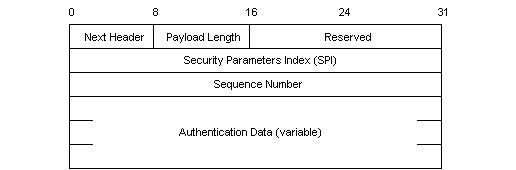
Figure 1 - IPsec Authentication Header (from [STAL99])
Three key fields in this header are the SPI field, the sequence number, and the authentication data. The SPI is defined above and contains the security association information under which this packet is to be processed. The sequence number is a continually increasing value and is used to help protect against replay attacks. The authentication data is a variable length field containing the integrity check value (ICV) or message authentication code (MAC) for this packet. The authentication data is calculated over various parts of the packet and depends not only on the data but also on whether the traffic is sent in transport or tunnel mode (discussed below) and whether there is any mutable data (discussed below) in the packet.
Mutability
Some fields within an IP packet header are modified by routers during transit from the source to the destination. Because of these modifications, these fields should not be included in AH's integrity calculation. For example, the TTL field must be decremented at each hop during transit. As such, if AH included it in the ICV calculation, the terminating endpoint would throw the packet away because the ICV calculated would not match the stored value in the AH authentication data field. The following fields are defined as mutable with respect to AH:
- ToS - Type of Service
- Flags
- Fragment Offset
- TTL - Time To Live
- Header Checksum
The above fields are not included in AH's calculation of the packet's authentication data.
Encapsulating Security Payload
The Encapsulating Security Payload (ESP) protocol provides for data confidentiality as well as authentication. ESP provides confidentiality by encrypting the encapsulated data (hence the name) using a negotiated ciphersuite. Interestingly enough a NULL encryption algorithm (see RFC 2410 and be prepared for a good laugh) can be selected that essentially provides no encryption to the data but does retain data integrity and optional authentication characteristics. In this way ESP can be made to behave exactly like AH. The header for ESP is shown in Figure 2 below.
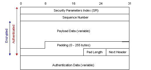
Figure 2 - IPsec Encapsulated Security Payload Header (from [[STAL99])
As with AH, the SPI identifies which security association is being used for this traffic, and the sequence number helps protect against replay attacks. The authentication data is the ICV for the packet; however, unlike AH, this data is placed after the payload data. For ESP, the authentication data is calculated over the entire ESP packet minus the authentication data field.
Modes
IPsec traffic can be sent in one of two modes: transport or tunnel mode. In transport mode, the IPsec header is inserted between the original IP header and the data payload. In tunnel mode the IPsec header is placed in front of the original IP header and a new IP header is placed in front of the IPsec header. The differences in the packet structure between these two modes is shown in Figure 3 below.
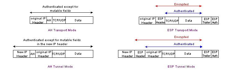
Figure 3 - IPsec Modes (from [STAL99])
Internet Key Exchange (IKE)
The Internet Key Exchange (IKE) protocol is designed to provide mutual authentication of systems as well as the establishment of a shared secret key to create in IPsec SA. The two original contenders for the IPsec key exchange system were Photuris (defined in RFC 2522) and SKIP (defined in http://skip.incog.com/inet-95.ps). Unfortunately due to various political considerations resulted in neither of these protocols being chosen and the IETF produced the IKE protocol instead.
IKE provides for mutual authentication using a long term key such as a pre-shared secret or a public key cryptosystem. It also provides for the establishment of a session key. IKE grew out of the Internet Security Association and Key Management Protocol (ISAKMP) framework. While ISAKMP is not really a protocol but a framework, the IETF did originally develop a protocol, OAKLEY, to work within the ISAKMP framework. IKE first appeared at roughly the same time as OAKLEY and borrowed from OAKLEY as well as another key exchange system, SKEME. Unfortunately, IKE suffers from complexity issues and the RFCs describing the protocol are difficult to read.
IKE Operation
IKE operates in two phases. Phase 1 provides for mutual authentication of the systems as well as the establishment of session keys and is known as the ISAKMP SA. Phase 2 provides for the setting up of the IPsec SA.
Before delving into how IKE works it would be helpful to review the Diffie-Hellman public key cryptosystem. This stems from the fact that IKE utilizes Diffie-Hellman to establish a session key.
Diffie-Hellman Key Exchange
The Diffie-Hellman public key cryptosystem allows two or more individuals to communicate with each other by enabling them to agree on a shared key even though all communications occur over a public network. This cryptosystem was first published by Whitfield Diffie and Martin Hellman in 1976 [DH76]. This system is based on the difficult of solving the discrete logarithm problem. In short, the protocol works as follows (using the classic cryptographic characters of Alice, Bob, and Eve):
- Alice wishes to communicate with Bob.
- In order to do so securely, she must establish a session key with Bob but the problem is that they must somehow agree on this shared key over an insecure medium, in this case the Internet.
- Eve wishes to monitor the communications of Alice and Bob.
Before starting the protocol, there are two additional parameters that must be discussed: p and g. p is a large prime number and g is an integer that is less than p. g must also meet some additional criteria, but for a basic understanding of Diffie-Hellman this criteria is not terribly important to know. To establish their shared session key Alice and Bob do the following:
- Alice and Bob both generate random numbers, R(a) and R(b) respectively.
- Alice computes the value S(a) = (g^R(a))mod p.
- Bob computes the value S(b) = (g^R(b))mod p.
- Alice and Bob exchange the values S(a) and S(b).
- Alice calculates (S(b)^R(a))mod p.
- Bob similarly calculates (S(a)^R(b))mod p.
Because the calculation is commutative (i.e. independent of order) both Bob and Alice will calculate the same value:
- S(b)^R(a) mod p = (g^R(b))^R(a) = (g)^(R(b)R(a)) = (g^R(a))^R(b) = S(a)^R(b) mod p
Both Alice and Bob have derived the same session key, which they can use to encrypt their future communications. All of this has been accomplished in plain sight of Eve and she cannot determine what the session key is. Of course there are problems with Diffie-Hellman, such as it's vulnerability to a man-in-the-middle attack; however, these problems are beyond the scope of this discussion.
Phase I IKE
Phase I exchanges occur as one of two modes or types of exchanges. One mode is known as main mode and uses six messages. This mode allows for mutual authentication of the parties, session key establishment, provides for endpoint anonymity and some flexibility in negotiating cryptographic parameters between the parties. The other mode, agressive mode, uses three messages and only provides for mutual authentication and session key establishment. Both modes are shown in Figures 4 and 5.

Figure 4 - IKE Main Mode
In IKE main mode the message order is as follows:
- In the first message, message 1, the initiator, in this case Alice, sends a cookie as well as a list of cryptographic algorithms she supports.
- Bob replies in message 2 with a cookie of his own as well as a list of the cryptographic algorithms that he supports.
- Messages (3) and (4) are the Diffie-Hellman exchange.
- In message (5), Alice reveals her identity to Bob and Bob similarly reveals his identity to Alice in message (6).
IKE aggressive mode cuts down the number of messages from six to three.
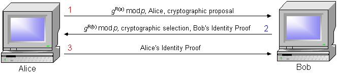
Figure 5 - IKE Aggressive Mode
- In message (1) Alice sends her public key along with a cryptographic algorithm choice. Bob sends back to Alice message (2). This message include Bob's public key as well as Bob's selection of a cryptographic algorithm and Bob's proof of identity.
- Alice responds by sending her proof of identity in message (3).
Once phase 1 of IKE has been completed, an SA has been set up and phase 2 begins. Phase 2 can be initiated by either side and will result in an IPsec SA. Phase 2 is sometimes refered to as a "quick mode" and is used to establish an ESP and/or an AH SA. The establishment of this SA may require another Diffie-Hellman exchange as well as the negotiation of cryptographic parameters. IKE phase 2 is shown in Figure 6.

Figure 6 - IKE Phase 2 Exchange
The phase 2 exchange occurs in three messages and consists of the following communication:
- Message 1: Alice sends the value X (the pair of cookies generated during phase 1), Y (a 32-bit number chosen by the phase 2 initiator used to distinguish the phase 2 session set-up), PCP (a list of proposed cryptographic parameters), a nonce, nonce(a) (a randomly generated value used to defeat "replay" attacks), an optional Diffie-Hellman value, g^R(a) mod p, and possibly an optional description of the traffic to be sent.
- Message 2: Bob sends X, Y, ACP (a list of accepted cryptographic parameters), SPI(b) (Bob's security parameters index authenticator), Bob's nonce, nonce(b), and optionally a description of the traffic to be sent and an optional Diffie-Hellman value, g^R(b) mod p.
- Message 3: The final message consists of the parameters X and Y as well as an acknowledgement from Alice.
Once IKE phase 2 is complete the IPsec SA is defined and traffic continues using that SA.
Implementing IPsec/IKE on Solaris
This article has provided a brief, high-level overview of IPsec, the IP security protocol, and IKE, the Internet Key Exchange protocol. Readers who are interested in a much more detailed examination of these two protocols are encouraged to read about them in the resources listed in the reference section below, particularly Network Security - Private Communication in a Public World and Cryptography and Network Security - Principles and Practice. These are two excellent references on the subject of IPsec and IKE and make significantly easier reading than the actual RFCs themselves.
The next article in this series will discuss the Solaris utilities, ipsecconf and ipseckey, and how they are used to configure IPsec VPNs using Solaris hosts as gateways, as well as how to secure traffic between two Solaris hosts.
To read the next installment in this series, click here.
Ido Dubrawsky has been working in UNIX and network administration field for almost 8 years. He is currently employed by Cisco Systems in the Cisco Secure Consulting Service as a Network Security Engineer.
References
[DH76] Whitfield Diffie and Martin E. Hellman, "New Directions in Cryptography", IEEE Transactions on Information Theory 22 (1976), 644-654.
[KPS02] Charlie Kaufman, Radia Perlman, Mike Speciner, Network Security - Private Communication in a Public World, Prentice Hall, Upper Saddle River, NJ. 2002.
[STA99] William Stallings, Cryptography and Network Security - Principles and Practice, Prentice Hall, Upper Saddle River, NJ. 1999.
|